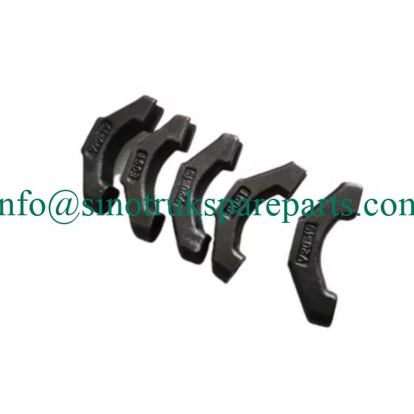
Genuine Sinotruk HOWO 082V04120-0024 Exhaust Valve Bridge
This authentic Sinotruk HOWO exhaust valve bridge (Parte No: 082V04120-0024) está diseñado con precisión según las especificaciones OEM exactas, asegurando un rendimiento óptimo del motor y una longevidad para los camiones HOWO. Diseñado para aplicaciones de servicio pesado, this critical component transfers motion from the rocker arm to paired exhaust valves, maintaining precise valve timing and sealing under extreme operating conditions. The hardened steel construction and precision machining ensure perfect alignment and minimal wear, making it an essential replacement for engine overhauls and maintenance.
Especificaciones técnicas:
Material: Heat-treated alloy steel (42-45 HRC hardness)
longitud: 98.5 ± 0.1 mm
Width: 25.0 ± 0.05 mm
Height: 32.5 ± 0.05 mm
Acabado superficial: Precision ground (Ra ≤ 0.4 μm)
Resistencia a la temperatura: -40°C to +300°C continuous operation
Load Capacity: Supports valve spring loads up to 2000 norte
Compatibilidad:HOWO A7, Serie T7H con motores WEICHAI WP10/WP12
Weight: 185 ± 5 grams
1. TRATAMOS A CADA CLIENTE COMO NUESTRO AMIGO, PEGARSE AL PRINCIPIO: BENEFICIO MUTUO Y GANADOR ;
2. UNA VARIEDAD DE ELECCIÓN DE PRODUCTOS: CALIDAD, MARCA, EMBALAJE;
3. LE RESPONDEREMOS SU CONSULTA EN 24 HORAS.
4.Proveedor de piezas de rendimiento profesional SINOTRUCK
5. ESTAREMOS EN SERVICIO 24/24 HORAS DEL DÍA LABORAL.
6. CULO: LE OFRECEMOS EL MEJOR SERVICIO POSTVENTA.

Installation Notes
Lista de verificación previa a la instalación:
1.Inspección de componentes: Verificar número de pieza (082V04120-0024) and check for cracks or deformation
2.Limpieza: Ensure valve bridge seats and contact surfaces are free of carbon deposits and debris
3.Measurement: Check valve stem heights for consistency (max 0.05 mm variation between paired valves)
4.Lubricación: Apply clean engine oil to all moving contact surfaces before installation
Pasos de instalación:
1.Positioning: Place valve bridge on exhaust valve stems with flat surface facing rocker arm
2.Alignment: Ensure bridge sits evenly on both valve stems without rocking or binding
3.Rocker Arm Installation: Install rocker arm and adjust to proper valve lash specification
4.Torque Specifications: Tighten rocker arm shaft bolts to 85 ± 5 Nm in specified sequence
5.Clearance Check: Verify valve lash (0.25-0.30 mm cold) using feeler gauges
Advertencias críticas:
Never reuse old valve bridges when replacing valves or performing engine work
Always replace valve bridges in pairs per cylinder to maintain balanced operation
Check rocker arm and valve stem tips for wear before installation
Verify proper valve bridge orientation to prevent binding or premature wear
Post-instalación:
Prime oil system before initial startup
Run engine at idle and check for unusual valve train noises
Re-torque rocker arm bolts after first 500 km of operation
Monitor valve clearances during initial break-in period